Pipe Modeling using AVEVA E3D software
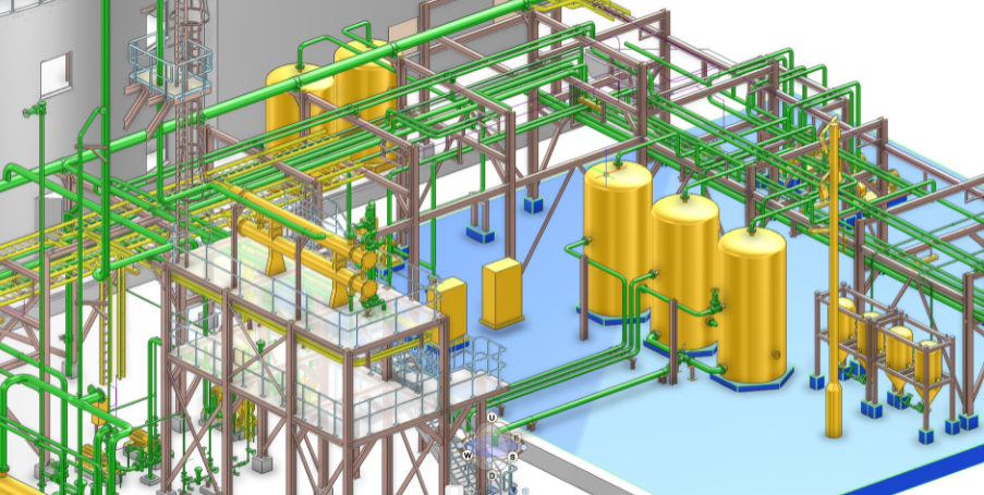
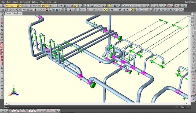
E3D is a 3D piping design software that integrated the good features of PDMS, AutoCAD, and SP3D into a single module. So, obviously, this is the next-generation most advanced software. Developed by AVEVA, The software is designed for a powerful 3-Dimensional design solution experience. Its clash-free multi-discipline design interface (Fig. 1) will reduce the design cost by minimizing rework and maximizing engineering and design efficiency. Moreover, the software is very easy to adopt and it provides the best project execution capabilities. The software is becoming very popular among piping designers circle.


Features of E3D
Some of the main features of this powerful 3D software are listed below:
- Aveva E3D combines all the best features of PDMS, Autocad, and SP3D.
- It is much faster and easier than other 3D software that is currently in market use.
- It is very user-friendly.
- E3D introduces the Auto-Route button (Refer to Fig. 1) which minimizes the time for the pipe routing.
- Laser scan models can be accessed directly in E3D without requiring LFM software to open the scan model.
- Introduced the Clip option which reduces the complication of complex projects.
- Structural, Primitive modification has been simplified.
- In-Draw 3D-model can be viewed by tool 3D-Edit
Pipe Modeling in E3D
Pipes are termed veins of any oil & gas plant. So designing pipes and modeling those following design codes and established best practices are very important. In this video tutorial, we will see how the piping is modeled using E3D software.
There are two videos. The first one explains the pipe modeling in the conventional method and 2nd video will explain the pipe modeling using the Auto-Route button.
Tutorial-1: Pipe Modeling in E3D
Tutorial-2: AutoRoute Pipe in E3D
Created by
Comments (0)
Popular categories
Piping Design Engineering : Basics
4Piping Design Engineering : Basics
2Latest blogs
Pipe Modeling using AVEVA E3D software
Tue, 17 Oct 2023
The Basics Of Piping Stress Analysis
Tue, 17 Oct 2023
Piping & Instrumentation Diagrams : P&IDS
Tue, 17 Oct 2023
Write a public review